
 Search Here
MISC
Parts List
Robot Forum
Chat
Member Pages
Axon MCU
Robot Books
Shop
Contact
SKILLS
How To Build
A Robot
Tutorial
Calculators
Mechanics
Programming
Miscellaneous
Robots
Space
HARDWARE
Actuators
Batteries
Electronics
Materials
Microcontrollers
Sensors
SCIENCE
Robot Journals
Robot Theory
Conferences

What is a servo? A servo, unmodified, typically has a rotation of some set amount. In other words, they cannot rotate continuously. This is because of the built in angle feedback control system. There is an internal potentiometer which is used to determine the angle which the servo is at. Pots, or variable resistors, cannot rotate continuously.
There is however a way to modify a servo so that they can rotate continuously. Why do this? Because although you lose position control, you gain speed control. Neat, huh? To do this, obviously the pot needs to be altered in someway. There is also a mechanical stop within the gears which needs to be removed as well.
A note to what will be tricky about this servo tutorial. There are many types of servos, and they all have variations in how the mechanics work. It will be too much work for a tutorial to cover all types, so I will cover the basic concepts instead. Fortunately, most servos made today are designed to be easily modified.
So the first step would be to open up the servo.
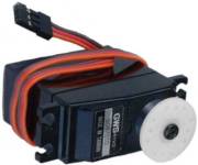
1) First make sure the servohorn is removed from the output shaft.
The servohorn attaches to the main output gear (the biggest gear), so removing it helps keep the gears from all
falling out when you open the servo up. Also, use a microcontroller to command the
servo to rotate to 0 degrees, the point between the maximum and minimum angle the servo can rotate to. You may also do this
step by hand, although it might not be as exact.
Note, if you are making The $50 Robot (or at least using the ATmega8 microcontroller), download this .hex file and upload it to your ATmega8. You dont need to compile anything, as I already did that for you. This program will tell the microcontroller to send a signal at 1.5ms, the signal your servos need to hold at the zero position.
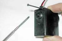
2) Next unscrew the four really long screws in the corners. Be careful not to strip the screw heads.
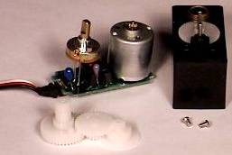
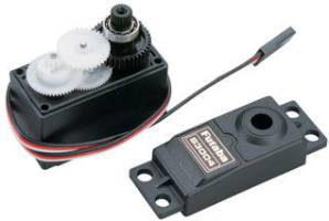
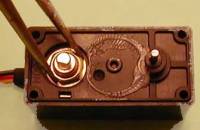
3) Now open up the top half of the servo. There are two parts that will open. The bottom half has the circuitry and wiring - make sure that remains closed. The top half contains the gearing. When opening, be careful not to have all the gears fall out. Memorize the gear locations just incase they do, so that you can reassemble everything. Make sure all the gears remain with the main part of the servo, with the exception of the large gear connected to the output shaft. Be careful not to contaminate the servo grease, as that would lead to an increase in gear wear.
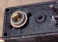
4) Now you need to find the pot. It is connected to and under the largest gear. You must pull off the main gear to find it.
5) Next we need to center the servo. Do this by plugging it in to your controller and send the signal required for it to go to 0 degrees. You should probably see the gears rotating without stopping. Now rotate the pot head (no, not that type of pot head) so that the gears stop rotating. It will probably be very sensitive so take your time. It is very important for this to be perfect. Get some superglue and glue the pot head to make sure it remains in place.
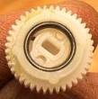
6) Now while the glue is drying, try to find the mechanical stop on the main gear. It will be something protruding that prevents the gear from rotating continuously when the gearing is assembled. Metal gears usually have a protruding metal pin, pull it out. Plastic gears have a protruding plastic peice that you need to cut off. Get a pair of snips and carefully cut it off. You might also have to file it down if your trim was not perfect. Rarely will it be. Don't damage the gear teeth during this process.

7) Attached to the gear that was connected to the pot is a little slot for the pot to fit in. Remove the slot from the gear. Chances are you can just pull it right out with a flathead screwdriver. This slot is so when the gear rotates, the pot will rotate with it. Keeping the pot in a fixed location tricks the servo to think it is at the same location.
8) Reassemble everything. Make sure the output shaft rotates continuously. Then send PWM to the servo. You will notice that by telling the servo to go to a particular angle, instead it will rotate at a particular speed. Neat, huh?
Not Working?
I just finished this tutorial but I'm having problems! Help!
Well you aren't alone. Try these forum posts:
http://www.societyofrobots.com/robotforum/index.php?topic=4400.0 http://www.societyofrobots.com/robotforum/index.php?topic=507.0 http://www.societyofrobots.com/robotforum/index.php?topic=1732.0 http://www.societyofrobots.com/robotforum/index.php?topic=1350.0
If you are still having problems, search the forum for other similar modify servo questions.
Society of Robots copyright 2005-2014