
 Search Here
MISC
Parts List
Robot Forum
Chat
Member Pages
Axon MCU
Robot Books
Shop
Contact
SKILLS
How To Build
A Robot
Tutorial
Calculators
Mechanics
Programming
Miscellaneous
Robots
Space
HARDWARE
Actuators
Batteries
Electronics
Materials
Microcontrollers
Sensors
SCIENCE
Robot Journals
Robot Theory
Conferences
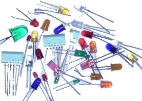
The LED or Light Emitting Diode
I am going to assume you already know that an LED is a very efficient, potentially high frequency, light
diode blah blah blah
. . . now for the more practical engineering stuff (so I won't bore you with
the basics) . . .
What makes a LED work? Inside each LED is a small bit of chemical that when electrons are passed through, it emits radiation (i.e. light).
By changing this chemical compound, you can in effect change the wavelength emitted - infrared, green/blue/red, near-ultraviolet, etc.
Be sure to read my tutorial on color sensors if you'd like to know more on wavelengths of light.
How to Use a LED
Firstly be aware that an LED is a diode, meaning that it is polarized. By convention, current
can only go from the anode (positive end) to the cathode (ground, or negative end).
How do you know which end is which? Note that the two wires on the LED are different lengths. The longer wire is always + and the shorter is -.
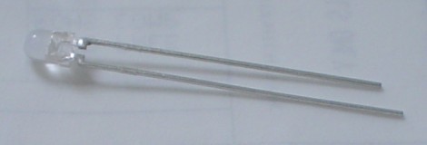
There are other ways to tell which lead is which. If you look from the top down, you will notice one side has a flat edge. That edge is ground. If you look inside, you can even tell by the shapes you see:

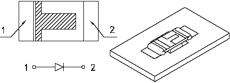
And what about surface mount (SMD) type LED's?
The same still applies, just the package is different. There are various
different ways to mark the poles of a SMD LED, so the best way to do it is just
check the datasheet:
How to select a Resistor
Why do you need a resistor in series with your LED? Because nothing is limiting current flow! It will fry
without a resistor. But don't fret over it - this is actually a feature.
Current is what determines how bright a LED is. More current means more light. LED current should typically be around 10 to 20mA. When current flows through the LED, a forward voltage drop of about 1.6V will develop between its pins, depending on the current. So this of this resistor as a valve - reduce it to increase LED brightness, or increase it to limit wasted power in your circuit.
First, find the datasheet on your LED. Scroll down towards the bottom until you see a few graphs:
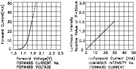
First lets start with the graph on the right. Select a desired brightness and use the graph to then determine the required current. For this example, lets choose a luminous intensity of 1.0, giving a forward current of 20mA.
This means that 20mA must flow through the LED to give you a brightness of 1.0. Now we need to calculate the forward voltage drop across this diode with this current. Look at the left graph at 20mA. Now you know the forward voltage drop is about 1.85V. Know that forward voltage drop is not just a function of current, but also LED color and temperature (because of the different LED chemistries):
| Color | Potential Difference |
| Infrared | 1.6 V |
| Red | 1.8 V to 2.1 V |
| Orange | 2.2 V |
| Yellow | 2.4 V |
| Green | 2.6 V |
| Blue | 3.0 V to 3.5 V |
| White | 3.0 V to 3.5 V |
| Ultraviolet | 3.5 V |
Next, determine what voltage you are applying to your LED - for example, if you are using a 5V regulator, then you are applying 5V. If you are using a 6V battery, then its 6V, etc.
Lastly, use this equation (derived from Ohm's Law, V=IR):
(voltage applied - forward voltage drop) / forward current = resistor value
(6V - 1.85V) / .02A = 207.5 ohms
LED's aren't very sensitive to resistor values, so don't worry if you must use a resistor 50% off of what you calculated.
PWM and LEDs
If you've ever tried using PWM
on LEDs you'd notice that the brightness % doesn't appear to linearly
correspond with the PWM %. For example, 20% PWM might give 80% brightness, and 40% PWM might give 95% brightness.
In reality its nearly linear, but your eyes are fooling you. If you want to use PWM
to linearly modulate the apparent LED brightness, you need to use an exponential matching equation
around x^2.5. For more info on apparent brightness, read up on the
Weber-Fechner Law.
Your eyes also have different sensitivities to different wavelengths, so the matching will be different for each color.
Other stuff about LED's
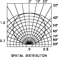
There are a few other important things you will notice in the datasheet of a LED.
The first is viewing angle. A wide angle means the light will not travel far, but will
instead spread out over a large area. A flashlight has a wide viewing angle, for example.
However a narrow viewing angle means light is more concentrated onto a smaller area, like a laser.
The datasheet will typically give you a single number, but some will describe in more detail on the light distribution per angle:
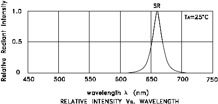
And of course a wavelength chart, telling you its peak value. Why is this chart important? Well suppose you were trying to match a LED to a color sensor - the optimal LED would be the one that peaks at the same wavelength as your sensor.
Society of Robots copyright 2005-2014