
 Search Here
MISC
Parts List
Robot Forum
Chat
Member Pages
Axon MCU
Robot Books
Shop
Contact
SKILLS
How To Build
A Robot
Tutorial
Calculators
Mechanics
Programming
Miscellaneous
Robots
Space
HARDWARE
Actuators
Batteries
Electronics
Materials
Microcontrollers
Sensors
SCIENCE
Robot Journals
Robot Theory
Conferences
(MADE SIMPLE)
In this tutorial, I will teach you about suspension systems, and a new type of suspension system I invented for robots that's very simple to make. (so give me credit and link back if you use it!)
But first, enjoy the video!
What is a Suspension System?
When building a robot you'd like it to be as simple as possible.
In most cases you'd never need a suspension system, but there are several
instances when a suspension system cannot be avoided:
your robot travels at high speed on rough terrain
When traveling on rough terrain, your robot is likely to bounce quite a lot.
This can wreak havoc on sensor data, joints, and potentially damage things
like gears.
your robot has more than 3 wheels
Unlike three points, four points are not guaranteed to always be on a plane.
If the terrain is uneven, such as if there were cracks in the ground
or small objects to climb over, one of the wheels will lift off the ground.
This will create a wobble in your robot, and potentially be a tipping hazard.
your robot experiences high frequency shock
Vibration can cause serious shock issues to your mechanical system as well as
laptop harddrive. Vibrations are often ~4x the force the robot joints normally
receive, causing fatigue and creep. Vibration can also loosen screws!
And of course, accelerometers and gyros won't work.
Adding a suspension system will dampen out this vibration.
your robot is micro-sized
For really really small robots, such as micro-robots, a traditional
suspension system is too complicated to make. My new technique scales
really well to the micro-scale.
Disadvantages of a Suspension System
The number one disadvantage of a suspension system is that they are
typically complicated. They involve many complicated parts, calculations,
a difficult assembly, and can cost a decent amount too.
A perfect example of a very complex suspension is the one here below designed by Honda. It has a large number of parts and requires a very complex mathematical analysis to design it:
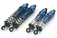
The example below is a pic of oil-filled shocks used on an RC truck. It also requires a decent number of parts, although mathematically its rather simple:
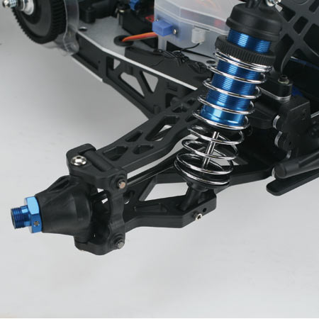
To answer your question, you can buy these springs at any RC website:
My Invention: Single Part Suspension System
To solve these typical suspension system problems,
I invented a single part suspension system that mainly involves designing materials to flex exactly
when/where needed. Yeap I invented it, so give me credit and link back if you copy the idea!
To demonstrate my suspension system, I used it on my Experimental Robot Platform. Here is what it looks like in CAD:
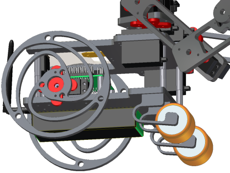
And in real life:
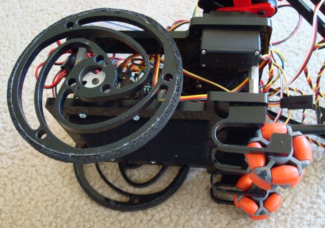
Look carefully at the large round wheels on the left, and the orange wheels on the right. They both use my single part suspension system design.
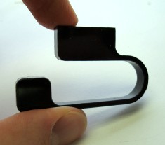
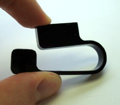
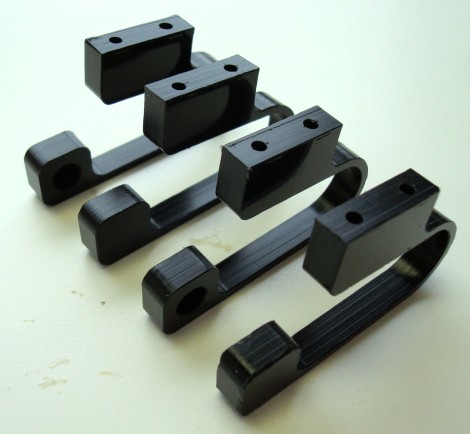
Lets start with the simpler design - the long beams attached to the small wheels. These beams are designed to deflect to be perfectly horizontal under the full weight of the robot. When the terrain under it changes, the deflection changes to conform with it. This is what the finished design looks like:
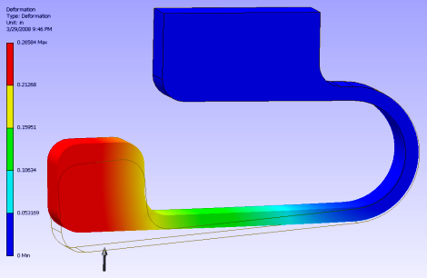
But its more complicated than it looks! You can't just guess a design and it'll 'just work'. Of course for simple designs, you can use basic stress analysis equations for bending beams. However I wanted more complex features, so I used FEA to simulate it. FEA isn't very reliable under large deflections, so it took me two iterations/experiments to get it right. The manufacturer of the delrin material I used also didn't release product specs, so I had to guess it based on typical values. I also didn't know the exact weight distribution of my robot to use in FEA, so I used the center of mass and weight calculator in my CAD software to get a good approximation of it.
Here is what the beam looks like in FEA:
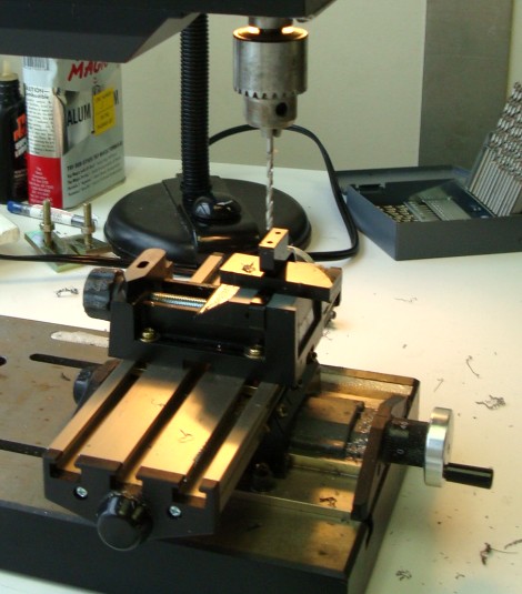
To make it I used CNC to cut out the profile. This made it easy to produce a whole bunch at once.
And then to screw it into my robot base, I drilled two holes into the top of each. I just used my tabletop drill press, with an attached X-Y table and vice clamp. Make sure it doesn't flex while drilling!
Wheel Suspension System
Using a similar design process as the above suspension system, I went even further
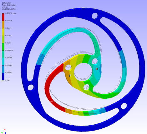
and created a single part wheel with a built in suspension system. The added bonus
is that it just looks really really cool. First I used FEA
to test and optimize the design:
A major problem that you will encounter when CNC'ing the flexible suspension systems is that they also flex when you are machining them! They also tend to vibrate in a mill, causing rough surfaces on your parts and scary loud noises. I designed the wheel with this in mind, but it still had serious problems. Do your best to secure the entire part during machining! If you have the option, a laser cutter would be a much better choice for these designs.
Here is what the completed wheel looks like:
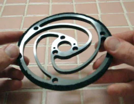
A perfectly cut wheel has very little friction. To improve traction, around the edges of the wheel I added a rubber material as described in my ERP updates documentation.
Omni-Wheel Suspension
My first suspension system using flexible materials was actually on
Fuzzy, an omni-wheel robot that used four wheels.
I mounted the servos on a very very thin sheet of aluminum that flexed when force was applied.
It worked really well on concrete and small cracks. Click the image to see what I did:

Sag Problems
Sagging in a suspension system is a problem you cannot ignore. In fact, I was forced to go through a third
and fourth iteration on the beam shaped suspension because I didn't account for sag =(
Sag is when over time the 'spring' in your suspension permanently settles into another position. On my 3rd iteration, I noticed serious sagging within just days of building the system. It was like putting a fat guy on a motor bike - you better believe the shocks will wear out!
There are several ways to design around sag. You can either stiffen up the spring and have it designed for 25%-75% more weight, setup an actively controlled spring modifier using something like servos, or set up some type of calibration device that you can tweak as the sag gets worse. To keep it simple I went with the first option - making it stiffer.
So finally on the 4th design, with a stiffer design, it lasted about a month before sag became noticeable. Its still working now, but at some point I'll have to swap them out for new ones. Keeping the robot weight off the suspension system during storage helps it last much longer. I'm sure certain materials will sag less too, yet still flex as needed, but I didn't investigate any further. I didn't want to over design it =P
Spring Damper Control
In theory, by carefully designing the shape and properly choosing the right material, you can even engineer a well
designed spring-damper controlled suspension . . . but I really wouldn't know where to start for that and what I did
worked fine. My FEA software couldn't do it for me. But I welcome you to try!
Disclaimer
A similar suspension design to that shown here is often used in MEM's devices. The
Mars rovers Opportunity and Spirit also use a similar wheel design, but it was meant only for
high force shock absorbance and not for full suspension. Lastly, there is the
Michelin Tweel
which works well for larger heavier vehicles - but I'm not sure how to make something like
that on the small scale. As such, I make the claim that I am the first to do this for a small scale robot!
Society of Robots copyright 2005-2014