
 Search Here
MISC
Parts List
Robot Forum
Chat
Member Pages
Axon MCU
Robot Books
Shop
Contact
SKILLS
How To Build
A Robot
Tutorial
Calculators
Mechanics
Programming
Miscellaneous
Robots
Space
HARDWARE
Actuators
Batteries
Electronics
Materials
Microcontrollers
Sensors
SCIENCE
Robot Journals
Robot Theory
Conferences
Fuzzy Logic Background
Computers define EVERYTHING in binary, a simple 0 or 1. Its either on, or off.
But the world isnt black and white, and not everything is simply true or false.
Fuzzy Logic (FL) is a numeric representation where the answer isn't just Yes or No,
but a grey Maybe.
It isn't where something is just very hot or very cold,
but instead could be luke warm, slightly chilly, etc. Humans operate much better
when fuzzily describing things, instead of simply using black and white for everything.
If we describe a temperature we might say 73 F, describing a food we might say
its a little tastey but could be better, or naming a color we might say dark green or light green.
To not have that range of descriptions would really hamper our descriptive abilities.
If robots are to ever out-perform humans, they need this ability too.
Disadvantages of Binary Logic
If a robot can only make decisions based on two extremes, its actions will also be
two extremes. Its like saying a robot can only go two speeds, 1mph and 30mph, and
no speed in between. If suppose your sensors give you values right between both extremes,
your robot would become very jerky bouncing between both those speeds. This is referred
to as oscillation, or when sensor data quickly bounces between two different case-based
(pre-defined) actions.
case based example:
-
sensor data can range between 0 and 255
sensor value bounces between 127 and 128 (middle of range)
10 is a made up tweak constant
case based pseudocode:
if (0->127)
go 1mph
if (128->255)
go 30mph
(note: On an 8 bit analog-to-digital converter, 127.5 is not possible)
Case-baseed oscillation is very bad for your robot - jerky motions can quickly wear and break mechanical parts, and will waste huge amounts of energy in acceleration/deceleration. You could perhaps write a long cased-based list of sensor to speed conversions, but that would be painfully long, and will waste memory space and processing time.
This is where fuzzy logic comes in, as fuzzy control allows very smooth transitions between actions with less code.*See Below
fuzzy logic example:
-
sensor data can range between 0 and 255
sensor value bounces between 127 and 128 (middle of range)
fuzzy based pseudocode:
speed = sensor/10
so on a scale of 0mph to 30mph:
if say your sensor = 127, speed = 12.7 mph
and if sensor = 128, speed = 12.8 mph
(Note: So this above example isnt exactly fuzzy logic, but an oversimplified equation so that you can have a basis of understanding the later equations in this tutorial. This equation can be considered fuzzy logic if all added arbitrary weighted values equal 1, as explained later.)
Not only is there a smooth transition between speeds, but the fuzzy program was much shorter and easier to write too! There are many other advantages.
Advantages of Fuzzy Logic
It is inherently robust since it does not require precise, noise-free inputs.
This means you can fudge (mmmmm . . . fuuuddggee) your equations with additional arbitrary constants in your equation.
New sensors can easily be incorporated into the system simply by generating appropriate governing equations. Often you can combine these equations into one.
Any number of inputs can be processed and outputs generated. Fuzzy logic is not limited to a few feedback inputs and one or two control outputs, nor is it necessary to measure or compute rate-of-change parameters in order for it to be implemented. Any sensor data that provides some indication of a system's actions and reactions is sufficient. This allows the sensors to be inexpensive and imprecise thus keeping the overall system cost and complexity low.
Fuzzy logic can control nonlinear systems that would be difficult or impossible to model as case-based. Fuzzy controllers are far simpler than knowledge-based systems. You do not need to be a controls expert, or fully understand the physics of your robot, to design a fuzzy logic control system.
Just like in PID control, fuzzy logic can be "tweaked" once the system is operating in order to optimize performance. Generally, fuzzy logic is so forgiving that the system will probably work the first time without any tweaking.
Fuzzy logic in most cases takes up significantly fewer lines of code in programming. Having memory issues? This may be your solution.
A disadvantage . . . There are exceptions to where case based programming is simpler to implement than fuzzy logic, such as when your mechanism can only work at a set of fixed outputs. Two examples would be gear changers, and navigating to fixed locations of objects centered around a robot arm. The following algorithms would still be possible, just highly complex and therefore not recommended. You can also use both methods, just mix and match to take only advantages of both.

Defining Fuzzy Logic With a Microcontroller
Most sensors used in hobby robotics operate on analog voltages, meaning that they output a fuzzy value between 0 and 1 (0V and 5V).
This output then goes to your microcontroller's analog to digital (ADC)
converter. The typical microcontroller uses an 8 bit ADC, which basically means it has a fuzzy range of 0 to 255
(0 being 0V and 255 being 5V). What exactly that 8 bit value means greatly depends on what your robot sensors
are and sense, so you would then need an equation to convert that 0-255 value into something
more meaningful - a color of an object, a distance to a target, a sound amplitude, etc.
You would then put that number into another equation (usually just multiplied or divided by some user defined tweak constant) to be applied to the robot actuators. As shown in the fuzzy logic example above, this process is fairly simple.
Example of Fuzzy Logic
A photovore robot would make a good example for fuzzy logic.
Your robot reads in sensor values, plugs those values into an equation, then takes the new values and sends them to the motors.
This conceptual robot has two photoresistors plugged into two ADC:
-
read left_sensor;
read right_sensor;
left_motor_speed = right_sensor * arbitrary_constant;
right_motor_speed = left_sensor * arbitrary_constant;
So basically, the more light a sensor gets, the faster the opposite side motor goes - making the bot turn into the light. Just 4 lines long! If/then statements are typically many more, and dont work so well.
The above example has a flaw though, in that if the robot is in a dark area neither motor will work. Another better example:
-
read left_sensor;
read right_sensor;
left_motor_speed = (left_sensor - right_sensor) * arbitrary_constant;
right_motor_speed = (right_sensor - left_sensor) * arbitrary_constant;
Still, only four lines of code, yet the robot can track any light at any brightness level. The above equation still has an oscillation problem when both sensors bounce near zero, and the robot wont move if both sensors are zero, but fiddling with the arbitrary constant and adding additional parts to the equation will solve all of that.
One last example, but one of many solutions:
-
left_motor_speed = (left_sensor - right_sensor) + arbitrary_constant/(right_sensor+1)^2;
right_motor_speed = (right_sensor - left_sensor) + arbitrary_constant/(left_sensor+1)^2;
Mixing Digital and Analog Sensors
Because fuzzy logic is great for sensor fusion, I should show you how to mix analog
and digital sensors.**See Below
Starting with the simpler above photovore code, lets add something in front of our equations to represent
digital collision sensors. This new code will allow the photovore
to back away intelligently during wall collisions.
-
left_motor_speed = (left_bumper*(-100)) + (left_sensor - right_sensor) * arbitrary_constant;
right_motor_speed = (right_bumper*(-100)) + (right_sensor - left_sensor) * arbitrary_constant;
Now if the bumper doesnt detect a wall (bumper = 0), then the algorithm acts like normal because the first term is zero. But if bumper=1 (wall collision), that first term becomes -100, meaning the motor will suddenly back up and away from the wall. You can also add a time delay in the code so the bot will back up for X amount of time, but for simplicity Id just add a resistor/capacitor on the sensor with X time constant. As you can see, no additional lines of code were added (other than read the new sensors). Its also no longer pure analog, but now has digital components too. Hows that for sensor fusion? ;)
Note that you could use other digital sensors, such as sonar or encoders, in a similar way. You only limitation is how mathematically clever you are . . .
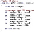
Negative Values in Fuzzy Logic
Some robot sensors, such as torque cells,
give both positive and negative outputs.
Now you may be thinking, 'I can only use 0->255, what if I want to include negative values?'
Well, your equation could scale your range into the negatives.
negative conversion example:
-
long signed int sensor_value; //variable type allows negative values in code
sensor_value=-255/2; //shifts everything into the negative, where 127 is 0
There are many other ways to do this that I wont get in to, but you get the idea. For further reading check out the programming variables tutorial.
What if your sensor returns positive AND negative voltage values? Then set your microcontroller ground to 0V and your sensor ground to 2.5V (by using a voltage regulator). This way anything below 2.5V represents a negative value, and anything above it represents a positive voltage. Make sure your sensor output values are between 0V to 5V or you may damage the ADC. To do this, carefully scale a non-inverting amplifier with the right resistor values and place between your sensor output and the ADC input.
*Addendum on the Definition of Fuzzy Logic
Many will argue that the above description is a very poor description of true fuzzy logic, and
they are correct. Fuzzy logic was never developed or intended for use on robots. Its use was
for describing things that didnt fit a binary description. As such, this is not true fuzzy logic.
However . . . The point of this tutorial is to adapt fuzzy logic into a functional,
practical, shortened control algorithm that you may use on your robot.
All equations do fit the definition of fuzzy logic, despite being permutated and
rewritten into more useful (yet non-standard) notation.
**Addendum on Analog Computers
Some may also argue that this is only an analog computer, of which they
are partially wrong. Many of the examples I gave use analog sensors, and have
analog outputs to analog motors.
In those cases, yes, it could be considered an analog computer.
But what about the case where I use an on/off switch? Or what about a case of using
binary solenoids for output, instead of motors?
This cannot be argued to be an analog computer in every case.
***Addendum on the Forum
Still disagree that this is true Fuzzy Logic? Check out my
forum post on fuzzy logic.
Society of Robots copyright 2005-2014