
 Search Here
MISC
Parts List
Robot Forum
Chat
Member Pages
Axon MCU
Robot Books
Shop
Contact
SKILLS
How To Build
A Robot
Tutorial
Calculators
Mechanics
Programming
Miscellaneous
Robots
Space
HARDWARE
Actuators
Batteries
Electronics
Materials
Microcontrollers
Sensors
SCIENCE
Robot Journals
Robot Theory
Conferences
It does not take long to figure out how useful a battery monitor circuit can be. A robot that self recharges can figure out when to dock in the charger, or how best to position its solar cells. Or how efficient it should run depending on distance away from a battery charger. You can also know if your robot needs to be charged between rounds in a robot competition without removing the batteries to check. Humans know when they are hungry, shouldn't your robot?
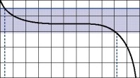
To operate this circuit, just follow the equation to determine the appropriate resistor value. Then plug Vout to your microcontroller analog input port. As your total voltage drops, so will the analog value. From there you can have your microcontroller decide what to do with the information. Perhaps turn an LED on or off, or even blink as a warning. Maybe a buzzing noise, or activation of a 'find charger' algorithm.
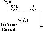
Battery Monitor Circuit:
|
To solve for resistor R, plug in to this equation: R = 50000 / (Vin / Vlog - 1)
Vin is your fully charged battery voltage.
|
There is however another slightly less direct way to determine remaining battery power. This works on the concept that if you put a finite amount of energy into a battery, it can only lose that same finite amount of energy and no more. So if you measure the energy going in and out, you will always know when your battery is running low. This is sometimes called "Gas Gauging", or "Fuel Gauging". What makes this difficult however is that typical batteries generally require 105%-115% recharge due to innefficiencies. You will have to test your battery to know. All of this requires a fairly complex circuit that I wont go into. So how do you do all this? Easy, buy an IC. The IC registers are then simply read from a microcontroller.
There are many IC's out there that can do this, each with different special features:
Texas Instruments: bq2010, bq2018, bq2019, bq2023
Maxim: MAX1660, MAX1780
Nat Semi: LM3822, LM3824
Dallas Semiconductor: DS2438, DS2760
For further reading, look at methods for measuring current use.
Society of Robots copyright 2005-2014