
 Search Here
MISC
Parts List
Robot Forum
Chat
Member Pages
Axon MCU
Robot Books
Shop
Contact
SKILLS
How To Build
A Robot
Tutorial
Calculators
Mechanics
Programming
Miscellaneous
Robots
Space
HARDWARE
Actuators
Batteries
Electronics
Materials
Microcontrollers
Sensors
SCIENCE
Robot Journals
Robot Theory
Conferences
Voltage amplifiers have various uses, but are usually used for boosting smaller voltages to larger ones. Suppose you have a sensor that has a voltage range of 10mv to 50mv. Few microcontrollers can measure this tiny amount! So what you would need to do is amplify this range to say 1V to 5V (since digital logic is usually 5V).
|
Where can you buy op-amps?
Check the ads on the right |
I would like to stress that voltage amplifiers are for amplifying low current/voltage signals (such as from force and torque sensors), not powering things like motors. It is for low current applications only. If you would like to power motors, consider getting power amps. Now that we are clear on uses, lets talk about how to make an amplifier. To make a basic voltage amplifier circuit, all you usually need are two resistors and an op-amp (Operational Amplifier). Op-amps are cheap IC chips available at any electronics distributer, often coming as dual packages and having other neat features.
Op-Amps have a special power source requirement. Typically it is 20V+ and 20V- to the positive and negative pins, respectively. However, your power source does not actually need to exceed your desired voltage output. For example, suppose your desired output is between the range of 0V and 5V. This is typical of any digital circuit for a microcontroller. You would then only need to apply 0V (ground) to the negative pin and 5V to your positive pin. You would usually not actually need a negative voltage unless you were to use an inverting amplifier (described below).
If you DO however need a negative voltage source, you can do this by placing batteries in series, and using the center connection as ground (shown here).
Non-Inverting Amplifier Circuit
-
Use this type of amplifier if you want to increase your low voltage to a proportionally higher voltage.
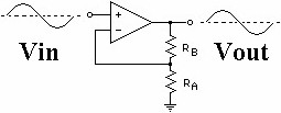
To choose resistor values, solve this equation:
(Vout-Vin)/Vin = Rb/Ra
Just plug in your desired Vout. Note that you cannot get a Vout higher than
your original power source, sorry.
Inverting Amplifier Circuit
-
Use this type of amplifier if you want to convert a positive voltage into a proportional negative voltage.
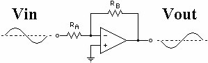
To choose resistor values, solve this equation:
(-Vin)/Vout = Ra/Rb
Just plug in your desired Vout. Note that you cannot get a Vout greater than
your original power source, sorry.
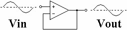
Voltage Follower (Buffer)
-
If you have a circuit which is driving a heavy load (such as a motor or a light)
and it is preventing your circuit from functioning properly, then you
would need a voltage follower. Voltage followers prevent things such as back EMF problems
or timer circuit problems. For example, Vout is always what Vin is. So it does not matter
what happens at Vout, Vin will always be at the proper voltage. This is useful if you
use a timer circuit to control a heavy load. Without the voltage follower, your load
would drain the capacitor rendering it non-functional.
Voltage Difference Amplifier
-
Suppose you have two different signals but all you care about is the signal difference
between both. So why would you get two different signals?
Some sensors have a + and - signal line and not just a single signal line.
Torque cells and force transducers
have dual signal lines, for example.
There are also occasions when you want to measure a scenario but the
environment significantly changes during your measurement (interference). What you would do is have one
sensor measure what you want plus environmental effects, and the other sensor
to just measure purely the environmental effects. To get a signal void of environmental effects,
you would just subtract the 2nd sensor value
from the first sensor value. Atomic Force Microscopes use this method as tiny environmental
temperature changes can affect results dramatically.
To choose resistor values, solve this equation:
Vout = R2/R1*(V2-V1)
V2 and V1 are the signals. Just plug in your desired Vout. Also note that R2/R1
is your gain value, meaning its how much your signal is amplified.
Society of Robots copyright 2005-2014