
 Search Here
MISC
Parts List
Robot Forum
Chat
Member Pages
Axon MCU
Robot Books
Shop
Contact
SKILLS
How To Build
A Robot
Tutorial
Calculators
Mechanics
Programming
Miscellaneous
Robots
Space
HARDWARE
Actuators
Batteries
Electronics
Materials
Microcontrollers
Sensors
SCIENCE
Robot Journals
Robot Theory
Conferences
Current Sensing
Current sensing is as it says - sensing the amount of current in use by a particular
circuit or device. If you want to know the amount of power being used for any
robot component, current sensing is the way to go.
Applications
Current sensing is not a typical application in robotics. Most robots would
never need a current sensing ability. Current sensing is a way for a robot to
measure it's internal state and rarely required to explore the outside world.
It is useful for a robot builder to better understand power
use of the various components within a robot. Sensing can be done for
DC motors, circuits, or
servos to measure actuator power requirements.
It can be done for things like
microcontrollers to measure
power performance in different situations. It can be useful for things like
robot battery monitors. And
lastly, robot hand grasp detection devices and collision detection. For example,
if the current use suddenly increases, that means a physical object is causing
resistance.
Methods
There are several methods to sense current, each having its own advantages and disadvantages.
The easiest method is using a typical benchtop DC power supply.
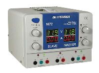
This device is somewhat expensive as it ranges in the hundreds, but they are very common and you can easily find one available in any typical university lab. These devices are a must for any electrical engineer or robot builder. Operation of this device should be straigtforward. Apply a voltage to your component, and it will quickly give a readout of the current you are drawing. Although this takes seconds and little effort to do, there are a few disadvantages to this method.
The first disadvantage is that it is not highly accurate. Usually they can only measure in increments rounded off to the nearest 10mA. This is fine for high powered applications where an extra 5mA does not matter, but for low current draw devices this can be an issue. The next disadvantage is timing. A benchtop power supplies only takes current measurements in set periods of time - usually 3 times a second. If your device draws a steady current over time this is not a problem. But if for example your device ramps from 0 to 3 amps five times a second, the current reading you get will not be accurate. The last major disadvantage is that there is no data logging ability - therefore you cannot analyze any complex current draw data on a computer.
The second method is using a digital multimeter.
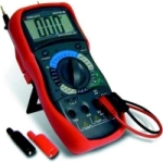
The digital multimeter is another commonly available device capable of analyzing many different characteristics of your circuit - voltage, current, capacitance, resistance, temperature, frequency, etc. If you do not already have one, you definitely need one to make a robot. It would be like cooking without heat if you didnt have one . . . For cost, they range in price from around $10 to about $100. The price depends on features and accuracy. To measure current, all you do is connect your two leads in series with one of your power source wires. But again, there are disadvantages to this method.
Like the benchtop power supplies, digital multimeters suffer timing issues. However, accuracy is usually an extra one or two decimal places better. Good enough for most applications. As for data logging, several available multimeters actually have computer linkup cables so that you may record current data to process later.
The last method is using a chip called a Current Sense IC.
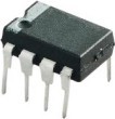
This ~$5 chip, using a really tiny resistor and a built in high gain amplifier, outputs a voltage in proportion to the current passing through it. Put the chip in series with what you want to measure, and connect the output to a data logging device such as a microcontroller. The microcontroller can print out data to hyperterminal on your computer, and from there you can transfer it to any data analyzing program you wish (like Excel).
This particular schematic below (click for the full expanded circuit) can measure current use of a servo. But it can easily measure current from any other device with no modification - and even multiple items simultaneously too! The capacitor is optional as it acts as a voltage buffer, ensuring maximum continuous current.
Society of Robots copyright 2005-2014