
 Search Here
MISC
Parts List
Robot Forum
Chat
Member Pages
Axon MCU
Robot Books
Shop
Contact
SKILLS
How To Build
A Robot
Tutorial
Calculators
Mechanics
Programming
Miscellaneous
Robots
Space
HARDWARE
Actuators
Batteries
Electronics
Materials
Microcontrollers
Sensors
SCIENCE
Robot Journals
Robot Theory
Conferences
- A 9V battery must connect to the battery + of the voltage regulator and ground of the voltage regulator.
- The 4.8V from the battery holder must connect to the ground of the black capacitor and the servo power bus.
- DO NOT connect the battery + end of the capacitor to the battery + end of 4.8V battery!!!!
STEP-BY-STEP ROBOT TUTORIAL
STEP 3b: CONSTRUCT THE CONTROLLER
Electronics, Continued
Continuing from Step 3A, I will now show you the
schematic we will use to build the circuit, followed by step-by-step instructions on how to wire your robot controller together.
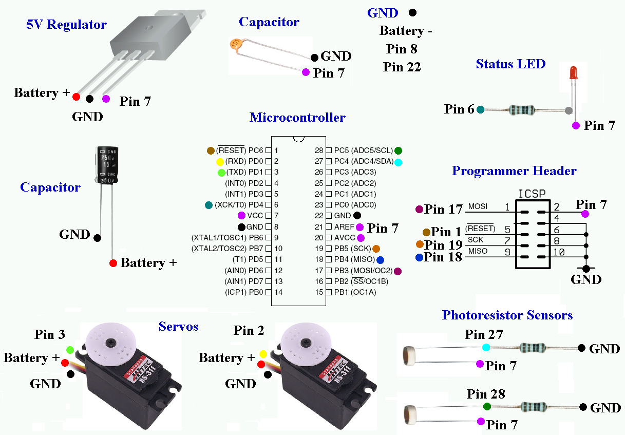
Now you need a schematic. A schematic is a wiring diagram that tells you where to attach wires to all the parts in your circuit. A schematic, to the uninitiated, can be a little overwhelming at first.
So instead of possibly confusing you, I invented what I call a colored dot schematic. I'm willing to bet a 3 year old can understand this enough to build the circuit . . . (apologies to all 3 year olds reading this tutorial)
Click the below image to open up an enlarged version. As you can see, I color coded each of the pins to determine which wire goes where. For example, all red dots should be connected to the + of your battery, and all purple dots should be connected together. If you're saying, 'gasp! I'm color blind!' Well, I numbered/labeled the pins too. Ill assume you know how to connect the dots, so I wont go into much detail into which wire goes where. =P
Note: If you are a dot-o-phobe, you can find a visual $50 Robot schematic on this forum post.
Now I must point out that this schematic (and the following tutorial instructions) is for if you decided to use an RC battery pack (or an assembly of batteries equal to 6V or greater). But if you went with the battery holder method, you must make the following changes:
This is the slightly modified schematic for battery holder users. The blue circles with a red dot in the center represent the 4.8V, while the red only dots represent the 9V battery connection. All this means is that the servos use power from the 4.8V pack (which can supply a lot of power), while the sensitive low power electronics use the regulated voltage from the 9V battery. Remember that all grounds need to be common.
If you have never soldered before, check google for soldering tutorials first. I've had a lot of practice soldering so I make it look a bit too easy. Feel free to practice on an unused part of your board first with scrap components. Also recommended YouTube solder tutorial videos.
Now lets begin building our controller!
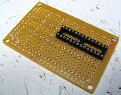
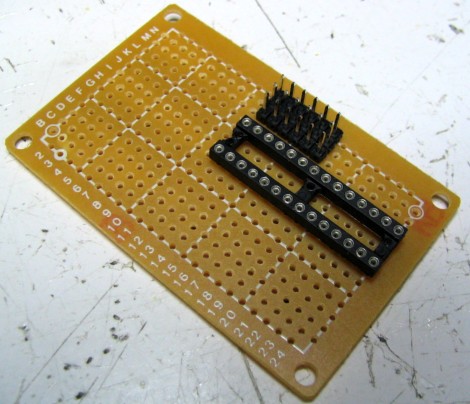
As shown, place the DIP socket into your perf board. DO NOT add the microcontroller IC to the socket yet.
It is not required, but I recommend copying the placement of all my components. If you look on the perf board, you will notice a number and letter grid system. This should be used as a guide to help you.
Turn the board over and solder it in. To do so, heat up the pin for about a second or two, then add the solder second. Make sure each and every pin is soldered. Also, make sure the side you are soldering has the copper padding - this makes it much easier!
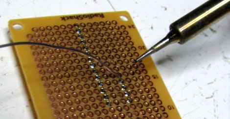
If you don't own a soldering iron, you can get a cheap one for around ~$10. RadioShack also sells them. If you want to make an investment, get a soldering iron that you can adjust the temperature on, and get nice tips. Remember, if you overheat the iron and apply pressure on the tip, the tip will dull and bend.
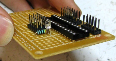
Place three of the 6 pin male headers as shown. These pins will be used in the future to plug in your robot sensors.
Then turn it over and solder each pin in.
In this step we will add more headers and a resistor (do one at a time!).
READ THIS POST before continuing!!! I designed the programmer header for an older programmer version, so chances are you will need to convert it to the new 6 pin header. It is easier to wire, it just requires a bit more of thought. Just check the number of pins on your programmer cable to know if you need 6 pins or 10 pins.
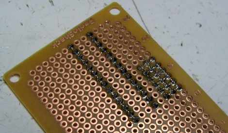
First add the three 5 pin male headers and solder them in. Also, I want you to connect all the pins as you see in the image (or schematic). For the pins closest to the DIP socket, connect each one individually. For the outer rows, connect them in parallel, as shown. These parallel rows are your power buses (they 'bus' power around).
Click on the image for an enlarged close-up. The pins will be color-coded to show how to connect them. Notice how I skipped a row for the 5 pin headers.
Next add two more rows of the 5 pin headers at the bottom right. Solder those in (pic not included). This will be for the ICSP connector of the programmer. Note that if you are using the more expensive programmer, you should check out this post concerning the different pinouts of the programmer.
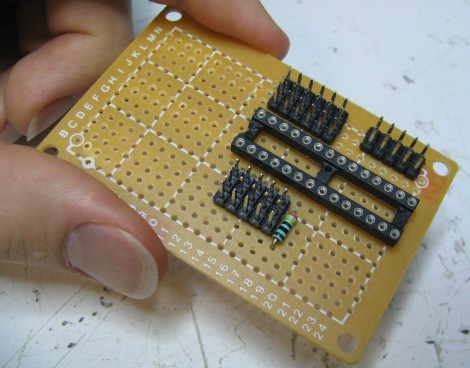
Now bend the leads on the resistor into perfect 90 degree angles.
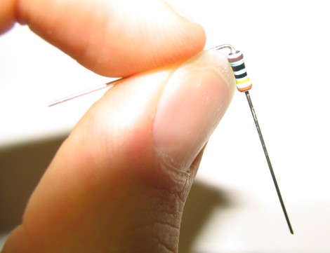
Add the resistor to the perf board, and bend the leads again as shown. Solder both leads, but DO NOT cut the leads! (not yet)
Now add the LED as shown, slightly above the board. Make sure the longer lead (+) of the polarized LED is on the side closer to the DIP socket. Solder it in, but DO NOT cut the leads! (not yet)
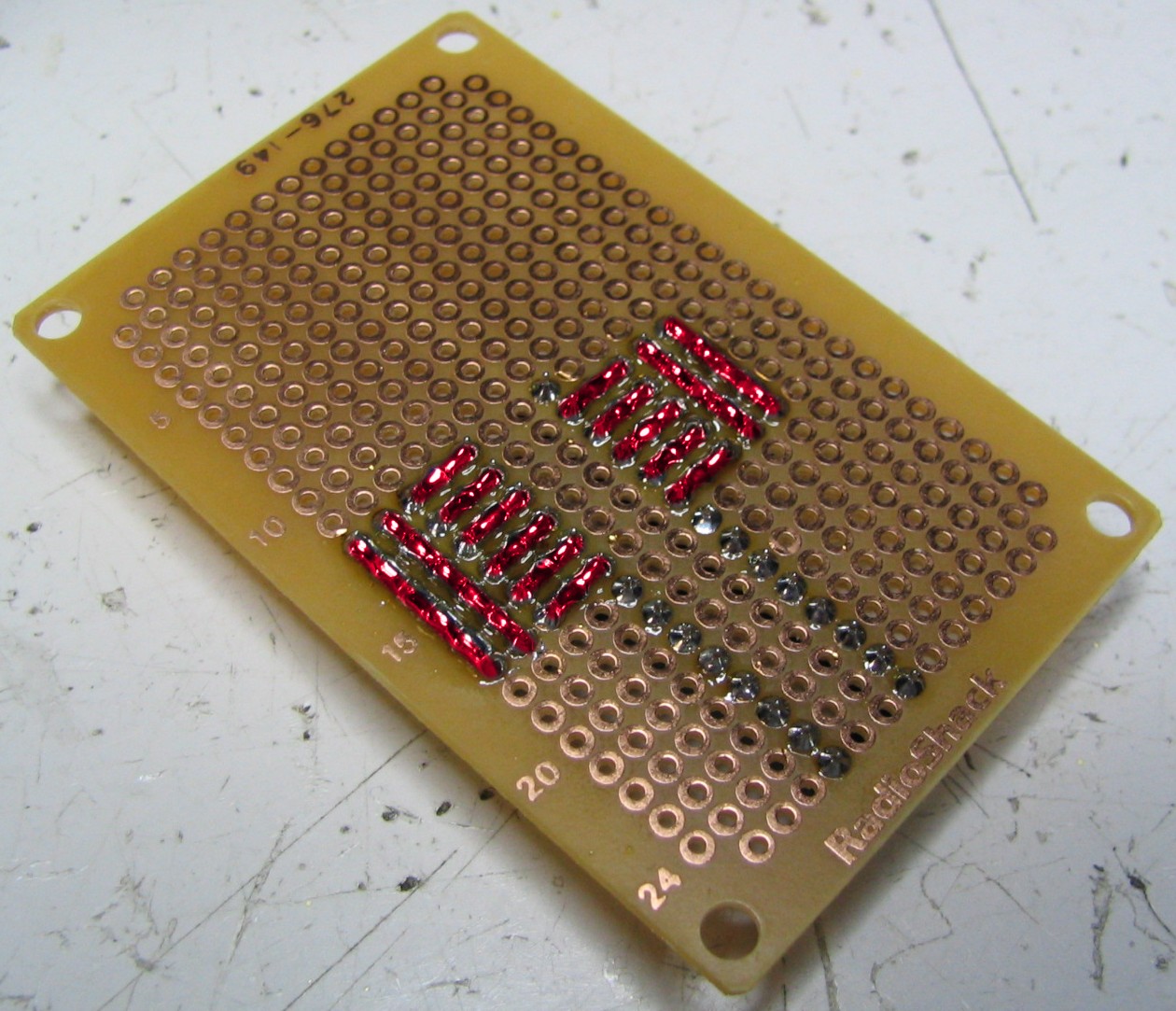
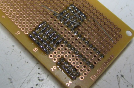
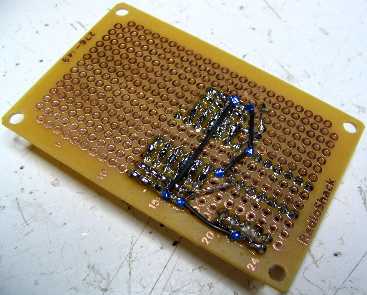
Turn the board over, and solder as shown. Click the image for an enlarged close-up. Red represents wires, and blue represents a connection with a pin. Reference the schematic if unsure. Notice how I bent the LED wire and resistor wire to connect several pins together? You can also use normal wire, but I use this method out of laziness and l337-ness all rolled into one. Make sure the wire doesn't touch the copper padding.
You may now trim the leads.
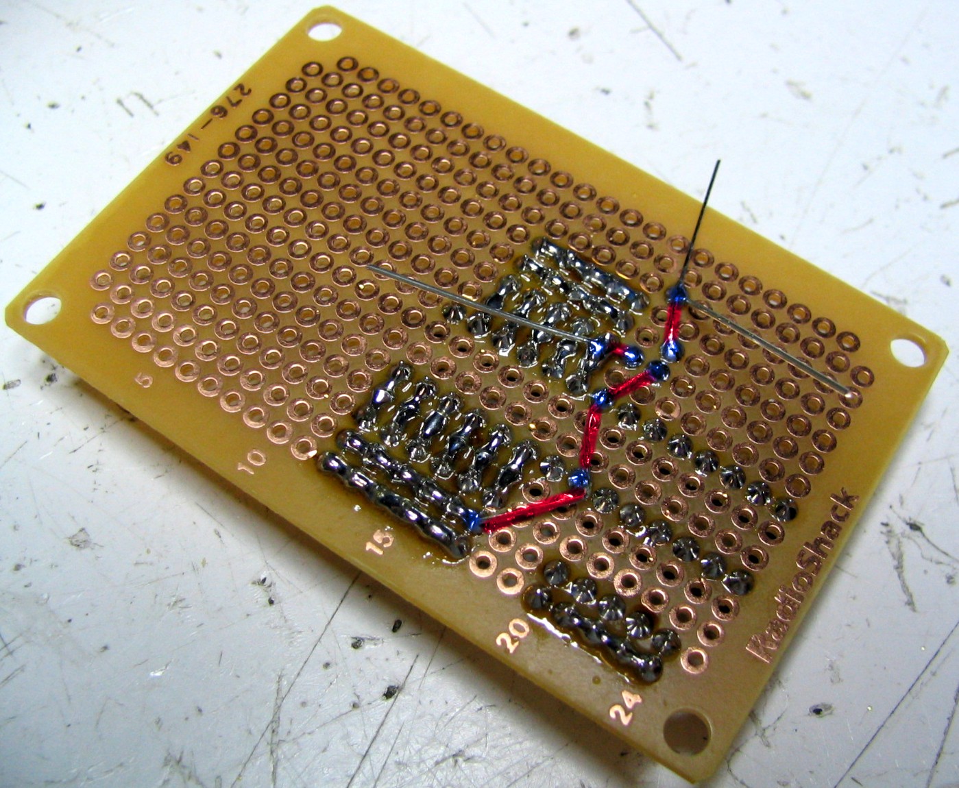
Now we will connect all grounds together. I like to use black wire to represent ground because it can save me a lot of confusion if my wiring gets messy. Click the image if you need an enlarged close-up. The blue coloring represents connections.
Relax, you are already half-way done!
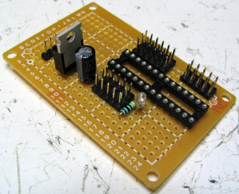
Add the big capacitor and solder the pins in. Make sure that the longer lead is on the side closest to the DIP socket. Notice the (-) sign on the capacitor? This is the negative side, which should have the shorter lead. This is important because the capacitor, just like the LED, is polarized and only works plugged in the right way. Make sure the capacitor negative lead is inline with the male header row farthest to the perf board edge. Check the schematic if unsure. (DO NOT CUT LEADS YET!)
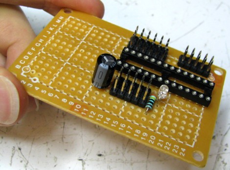
Add in the voltage regulator. Make sure you do it as shown! The middle pin of the regulator (ground) should be inline with the negative lead of the capacitor (ground). You may trim the three voltage regulator leads after soldering them in.
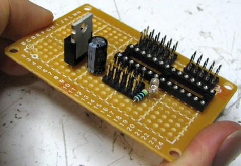
Now add the 3 pin header. If you are using the single cell batteries (ie 4.8V battery holder), you would not need this header. But if you are going to use a RC battery pack, you could plug it directly into this three pin header. DO NOT CUT THE LEADS YET!
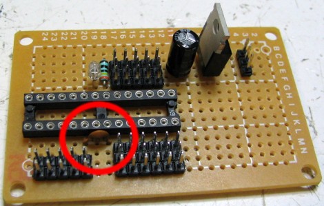
note: There is a minor mistake I made here that I want to point out. For the 3 pin header, shift it one hole over to the right (from holes CDE to DEF). Have it so the farthest left pin is connected to ground and the middle pin is connected to power.
Now turn the board over and solder as shown. I bent the leads of the capacitor to use as connecting wires, but you can also make the connections using real wires. Be aware that these two wires will receive 100% of all current in your circuit - it could be several amps! Click the image to see an enlarged close-up (red for wires and blue for connections to pins).

Note for those using the 4.8 battery holder:
You want the power from the 9V only going to the electronics, and the power from your AA battery holder going only to the servos.
They both share ground, but the + voltages are different and so shouldnt be connected.
As such you need to make a small correction to the circuit.
Please see this graphical representation. First, dont solder where the green X is. This seperates the two different power sources. Second, you want the large black capacitor to connect between ground and the servo power bus. Do not have it connected to the voltage regulator input pin. Third, attach the AA power and ground as shown in the graphical representation.
If you are using a 6V battery pack, you can ignore this note.
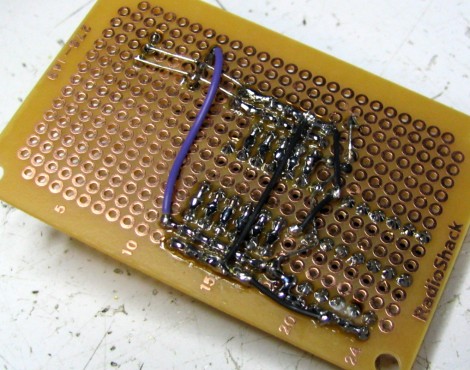
While you are at it, add in this purple wire. This wire will transfer the output 5V from your regulator to the middle row of the sensor power bus.
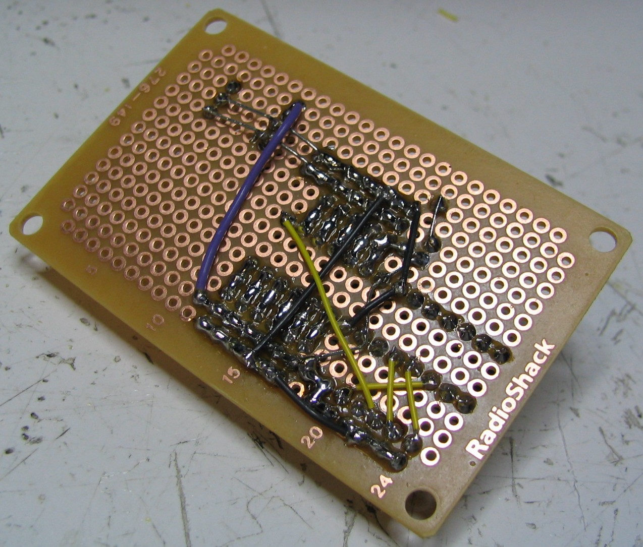
Now we want wire up the Programmer ICSP Header (see schematic). I used thin yellow wire for this, so as not to confuse with ground or 5V power. Click to enlarge.
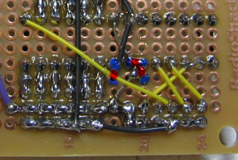
Finally, we will add a ceramic capacitor (non-polarized) between pins AVCC and GND, and connect AVCC directly to AREF.
Flipping it over, here is a close-up of the connections.
You are almost done (yaaaaay!)
Click to continue to Step 3C >>>.
We will then test your circuit, connect it to your PC, and build the robot sensors.
Society of Robots copyright 2005-2014