
 Search Here
MISC
Parts List
Robot Forum
Chat
Member Pages
Axon MCU
Robot Books
Shop
Contact
SKILLS
How To Build
A Robot
Tutorial
Calculators
Mechanics
Programming
Miscellaneous
Robots
Space
HARDWARE
Actuators
Batteries
Electronics
Materials
Microcontrollers
Sensors
SCIENCE
Robot Journals
Robot Theory
Conferences
=== Solar Panels ===
Introduction to Solar Panels for Space Balloon Flights
Solar panels get a lot of hype in the pervasive 'go green' hippy culture of today.
And given that NASA puts solar panels on many of their space robots, why can't we?
The benefit of solar panels is that you no longer need to lug around the weight of a big battery, and you never run out of 'juice'. You can in theory run the robot indefinitely.
But any engineer worth his water weight would know there are huge drawbacks to the use of a solar panel: low current, low voltage, and no power when the sun doesn't shine.
So what's better for space blimps: batteries or solar panels?
There are always trade-offs, there is no absolute 'better'. There are only solutions more appropriate than others to the required design restraints.
Solar Panel Capabilities
An engineer needs scientific data to make design decisions. For example:
Does the solar panel need to be perpendicular to the sun at all times to get light? Does light reflected off the atmosphere help when the solar panel isn't pointed at the sun?
Given X surface area of a solar panel, what voltage and current would be expected from a typical solar panel?
What is the typical power requirement of my electronics, and given that the solar panel is not always facing the sun, can it still power everything?
How does atmospheric temperature, and lack of an atmosphere, affect efficiency?
These are the questions I set out to answer with these experiments.
Mounting the Solar Panel
The solar panel was sandwiched between the cloth of the cooler and a transparent sheet
of plastic. The plastic was attached using zip-ties, and the solar panel was simply
slid right in between.
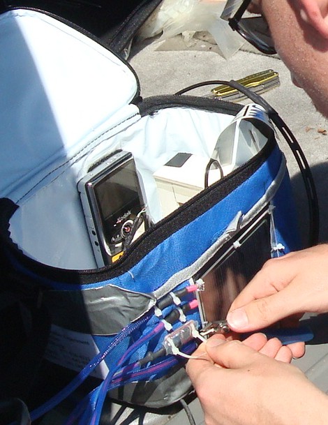
I also mounted a temperature sensor, an infrared light sensor, and a visible light sensor next to the solar panel. These sensors will let me know if the solar panel was facing the sun when it was collecting energy, and what the intensity of the light and temperature was.
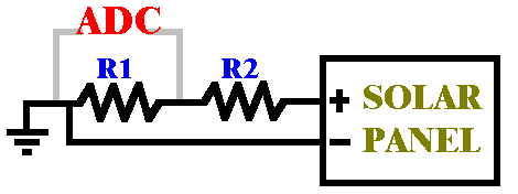
Current and Voltage Measurement
Voltage measurement was very easy to do. I set up a two resistor voltage divider,
where the voltage drop across the second resistor was sent to the ADC port of my
Axon Mote microcontroller. A multimeter was used to calibrate
the circuit to the ADC readings.
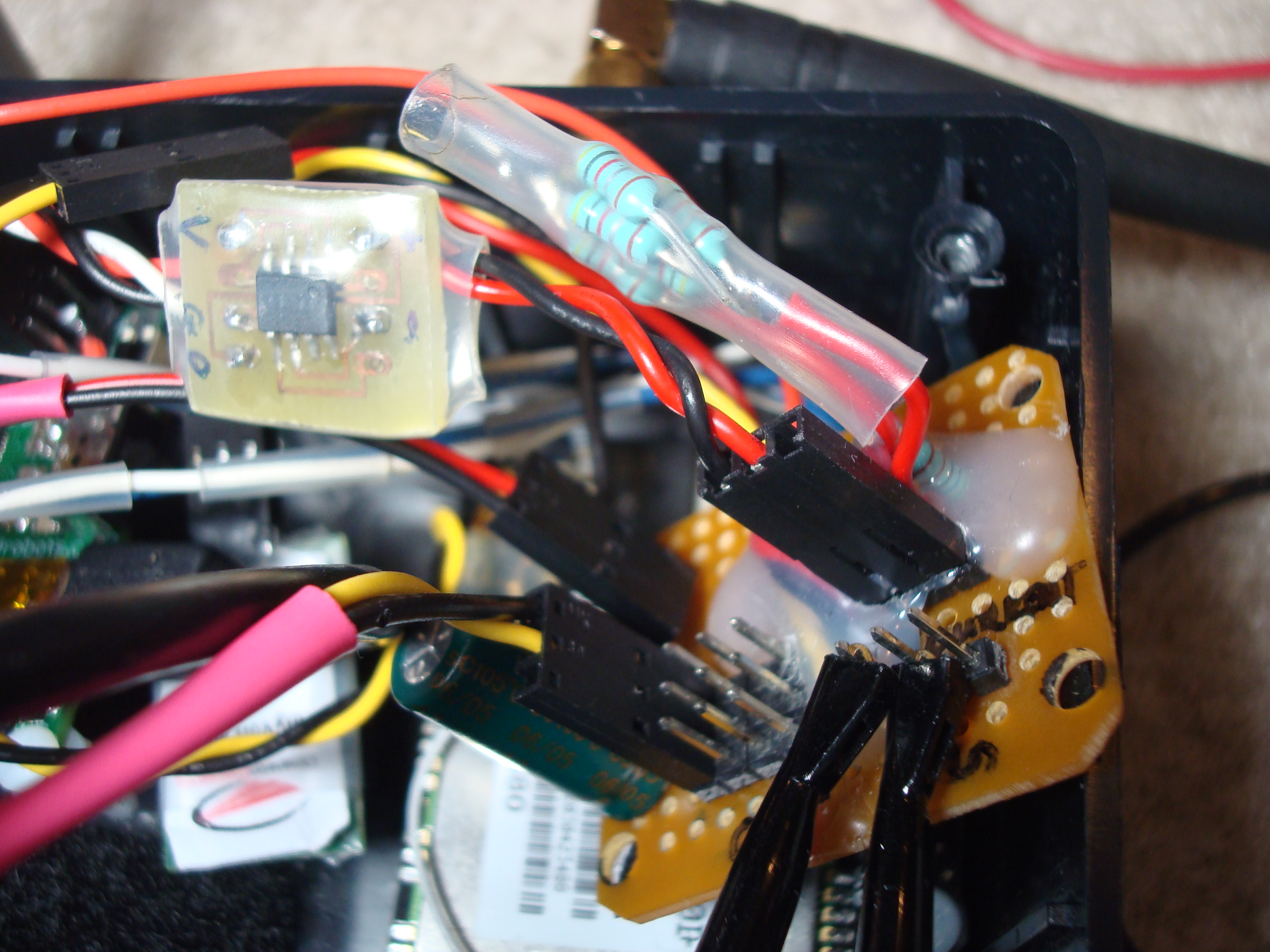
Current measurement was much trickier, as it required a current sensor. To measure current, I used the MAX4173 FESA current sensor along with a ghetto sense resistor (ghetto because I didn't have enough time to find a proper sense resistor).
The Rs+ of the chip was connected directly to the output + of the solar panel, while the Rs- was connected to the + of the rest of my circuit. As such, ALL current that left the solar panel would first pass through the current sensor IC.
If you click on the below image you'll see my current sensor circuit. The tan-colored square board on the left is the MAX IC, and that strange collection of five resistors soldered together in parallel on the right is my ghetto sense resistor. I was able to customize the resistor for maximum sensitivity by simply adding or subtracting resistors to the collection. Once completed, everything was heat-shrinked and hot-glued to prevent any accidental shorting or wires coming loose.
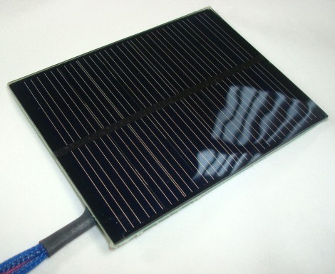
Solar Panel Characterization
The cheap $3.50 solar panel I used was rated at 1W and sized at 75mm x 100mm. At that price, I couldn't
resist getting it just to try it out (summer of 2010).
Before even sending it out to space, I had to determine what it was capable of. Attempting to mimic sunlight, I got out my incandescent light bulb lamp and shined it directly at the solar panel. I measured both current and voltage with and without a load.
note: The sun in space is very bright. Testing your solar panel with a lamp on top of it won't be enough. There are expensive 'solar simulator' devices used to test solar panels that you can use, or run your tests outside on a bright sunny day. As such, the results later in this tutorial will often max out due to me under calibrating the sensors.
| Solar Panel Output | ||
| loaded | no load | |
| voltage | 2.2V | 6.5V |
| current | 90mA | 0mA |
As you can see, the solar panel cannot supply more than about ~60mA for a 3.6V circuit. It also couldn't supply 1W as claimed - much closer to 0.2W for this test.
So how much power do my electronics require? Well, running everything together as realistically as possible from a battery, the average current draw was 185mA and the max during spikes was 362mA. This would mean that my solar panel would need to be 5x bigger (or 5x more efficient) for it to be feasible to use. And that's assuming the panel is always facing the sun!
note: These power requirements are only for my science package, and do not account for the much higher power requirements of the cameras and transmitters. They each have their own independent batteries, and rightly so.
conclusion: Although this solar panel sucks balls, it does give me a good idea of how the trip to space can affect solar energy collection. It can inform the selection of a better solar panel for a future launch.
Controlling the Solar Panel Voltage
As the light shining on the solar panel isn't steady, the voltage of the solar panel won't be steady either.
Therefore electronics need to be added for voltage stabilization.
Capacitors in theory could be used to stabilize a voltage. But if the solar panel voltage drops below the capacitor voltage, then the capacitor shorts into the panel. Bad!
So then what you add is a low dropout diode so that current only flows one way, ie from the panel into the capacitor. However when the solar panel voltage is lower than the capacitor voltage, no current flows at all - wasting all the energy in the panel.
The solution is to use a dc-dc converter circuit. That means that whatever the input voltage is, it always outputs a higher stable voltage. It does this by dropping current to increase voltage, at the cost of efficiency. The converter I used is the AnyVolt Micro by Dimensionengineering.
The input came from the Rs- of the current sensor, while a selected output of 5.1V was sent to VCHG of the DroneCell.
The DroneCell, which is what I used to send text messages to and from the balloon, has a built in LiPo charging circuit. The VCHG pin requires ~5V which comes directly from the AnyVolt. The LiPo I used, a 3.6V battery with built-in protection circuitry, then connects directly to VBAT of the DroneCell.
With this configuration, any power left over from the solar panel then gets used to safely recharge the battery.
note: More recently there are chips you can buy which are specialized for use in 'energy harvesting'. Costing you only ~$15 in parts, they can be directly connected between the solar panel and battery with very high efficiencies.
Solar Panel Results
During the entire flight, all data pertinent to solar panels were recorded. Click the below image to enlarge.
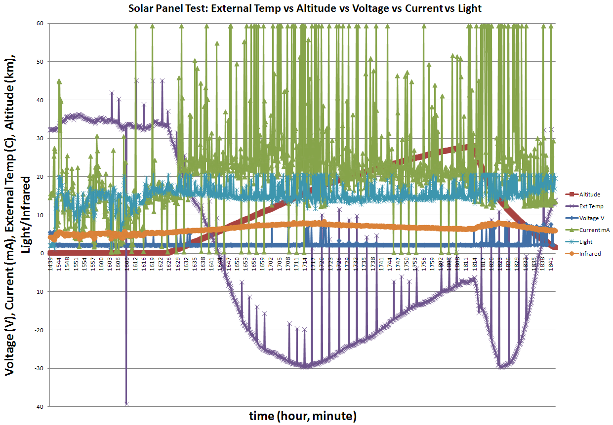
There is a lot going on in that chart so let's break it down into components.
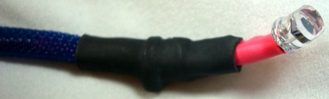
First, a look at infrared light (orange). Interestingly, the maximum intensity of infrared was detected within the jet stream. I'm not entirely sure how to explain this. My data-logging system only recorded maximum values during set time intervals, so maybe as the package was swinging around perhaps it was more likely to point directly at the sun. For the next flight I should program it to record averages and see if I still see this result or not. This below image is the IR sensor I used.
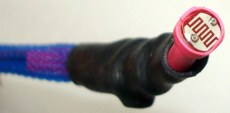
Now look at visible light (teal). Unfortunately the sensor maxed out too often to consider it good data or to draw solid conclusions - a result of under calibration. The issue will be fixed for the next flight. This below image is the visible light sensor used (it's a photoresistor).
The next thing to look at is external temperature (purple). Although a general trend is clear, there appears to be strange blips in the external sensor data. This is likely due to over-voltages being sent to the ADC from two other under-calibrated sensors. Also note that the temperature sensor hasn't been properly calibrated, as the real external temperature went as low as -40C.
But these are minor fixable issues. You can clearly see that the temperature is the coldest while the balloon is in the jet stream - not when it is in space. More information on temperature sensing can be found on my space temperature measurement tutorial.
It is already known that solar panels are most efficient when they are cold - hot temperatures cause semi-conductors to become inefficient. This becomes obvious when you look at the current measurement (green). Unfortunately the sensor maxed out yet again due to under calibration (sigh), but you can clearly see it maxes out much more often the colder the air got. This means the solar panel is most efficient and supplies the most energy when the balloon is in the jet stream.
The more current you drain from a solar panel, the lower its voltage drops. Inversely, when more current is being supplied than is needed, the voltage goes up. You can see this by looking at the voltage measurement (blue). As mentioned earlier in this tutorial, the circuit requires more current than the solar panel can supply. Although usually below ~2V, you'll see on rare instances little voltage spikes up to ~7V. This happens when the infrared and visible light is at its highest and the temperature is at its lowest.
Possible Future Experiments
There are other methods of measuring light. For example, although an LED is designed to emit light, it can also discharge a current when
light is shinned onto it.
The advantage is that different color LED's can measure different wavelengths of light. To try this, first place a capacitor across the leads of the LED.
Use 0.001 uF, unless it is a blue or UV LED in which case use 10-15 pF. Then use your microcontroller ADC to measure the voltage across the capacitor.
It may or may not need an amplifier. I haven't actually done this, but it sounds like a fun experiment for a future launch.
One could also look into using a photometer, a specialized color sensor, and color filters over photoresistors. If you don't want the sensor affected by directionality, i.e. whether it is pointed at the sun or not, light sensors could be put inside a ping pong ball for light diffusion.
Another unanswered question, which could affect previous results, is how temperature affects a photoresistor. The fact that I don't know this could put into doubt my results. To test this, I can set up an experiment where a flashlight shines onto my sensor in my freezer, and then see if the reading changes over time as it cools. If it does change, I may have to write a temperature calibration equation to compensate. The flashlight must be well insulated as it too will be affected by temperature.
Conclusions
Solar panels are more efficient on balloons than they are on the ground due to increased light and reduced temperatures.
A solar panel 4x larger can fit on the balloon, and might be able to create an energy neutral situation allowing the
scientific payload to work indefinitely (until nighttime, that is).
I plan to correct all the little calibration issues and fly it again likely in mid-2013. Anyone want to donate a solar panel? =P
update: A tutorial on how to power an Axon Mote using a solar powered phone charger (or any phone USB charger).
Society of Robots copyright 2005-2014